


Georeferencing: How it works, and what it means for GIS workflows
Working with spatial data isn’t always straightforward. Rasters may be in the wrong location, coordinate reference systems (CRS) may be mismatched, and images might not align with other layers. Unfortunately, not all location data is ready to map and analyze.
Raster files like aerial photography and satellite imagery contain rich geographic detail, but on their own, they don’t include the location details a geographic information system (GIS) needs to flesh them out. Without coordinates, the platform has no reliable way to place imagery inside a coordinate system or align it with other datasets for spatial analysis.
Think of a scanned paper map from a city archive. You can see streets and landmarks, but the file itself doesn’t tell a GIS where any of those belong in the real world. That gap immediately creates problems: The map might sit in the wrong location or fail to match the scale of nearby layers. Once that happens, comparisons and conclusions become questionable.
Georeferencing solves that problem. In this article, we’ll explore how georeferencing works, who uses it, and where it fits into mapping and raster-related workflows.
What’s georeferencing?
Georeferencing is the process of assigning real-world geographic coordinates to raster data. In other words, it takes an image that only shows geography and ties it to a known spatial reference or coordinate system so the GIS can place it on Earth. That way, the platform puts it where it belongs on the planet instead of treating it as a picture with no spatial position.
Some geospatial data formats, like scanned maps and historical imagery, have no spatial reference information at all. Others, like aerial photographs, satellite images, and digital elevation models (DEMs), may or may not include coordinate metadata to place them correctly.
But that isn’t a flaw in the file. Instead, it reflects how the raster was created, scanned, or exported. A scan saves the content visually but doesn’t automatically preserve a usable coordinate system for GIS work.
How does georeferencing work?
In GIS workflows, georeferencing means taking an unaligned raster through four stages until it becomes a fully usable map. Here’s how it’s done.
Choose and place control points
Georeferencing starts with ground control points (GCPs). These are places you can clearly recognize on the raster, like a road intersection, building corner, or river bend. When you click those spots on the image, the georeferencing software stores them as anchor points to use later. Eventually, the tool has a set of points that tie the raster to the real world.
Link control points to real-world map coordinates
Next, connect each control point to its true location on a map, either by clicking the feature on an existing georeferenced map or by entering the coordinates directly. The software turns each match into a source-and-target pair. Now, you’ll have a list of linked points that tells the GIS how image space relates to geographic space.
Apply a transformation to align the raster
Once enough point pairs are in place, the software uses them to calculate a transformation — how the raster should rotate, stretch, or wrap so it fits the target map. Different transformation types suit different kinds of distortion, and if the chosen method doesn’t match the project, the raster might warp or line up incorrectly. Here are the most common types:
- Affine transformation: Best for simpler corrections. It can scale, rotate, and skew the raster while keeping straight lines straight and parallel lines parallel.
- Projective transformation: Useful when the image has perspective distortion, like an angled photo. Straight lines remain straight, but parallel lines may no longer stay parallel.
- Spline transformation: Useful when the source image has uneven local distortion. It forces the control points to match very closely, though the areas between those points may stretch more.
- Higher-order polynomial transformations: Better for more complex warping, like curved paper maps or images with broader distortion patterns. These can handle more complicated bending, but they also need more control points and can introduce more distortion at the edges.
Resample and export a new aligned raster
After transformation, the software creates the final output raster. Since the pixels in the new position don’t line up perfectly with the old ones, the GIS has to calculate new pixel values through a process called resampling. The software may use the nearest neighbor to preserve original values, while bilinear and cubic methods are better for smoother, continuous data. The result is a new aligned raster, often saved as a GeoTIFF or DEM.
Key components of georeferencing
A georeferenced file may look accurate at first glance but can still be slightly off in ways that affect measurements and decisions. The final layer’s reliability depends on the following technical components that make it analysis-ready.
Ground control points
GCPs are the locations for anchoring the raster to the real world and control how well the GIS places information. They’re spots you can easily and clearly identify on the image and on a trusted reference layer.
Georefencing works by locating points on the layer and assigning known coordinates, so adding more improves the result. If the points are inaccurate, too few, or congested in one area, parts of the image may drift out of place even if the overall result looks acceptable at a glance.
Coordinate reference system
A CRS is a system that tells the software what the coordinates mean and where they belong on Earth. It controls how software places the raster on the map and how it lines up with other layers. If you assign the wrong CRS, the raster may appear in the wrong place or fail to align with roads or boundaries, even if the image looks fine.
Geodetic datum
A geodetic datum is the base reference behind the coordinates. It’s a system with a reference surface with known locations of surveys and maps. If the datum is wrong or doesn’t match your other datasets, the raster can appear slightly shifted even if GCPs and CRS seem correct.
Who uses georeferencing?
Many industries rely on spatially accurate raster data. Here are some georeferencing examples:
- Environmental science and climate research: Aligning satellite imagery and other remote sensing rasters to detect changes in weather, land cover, and climate-related analysis
- Urban planning: Connecting aerial imagery, scanned plans, and historical maps with zoning and infrastructure
- Agriculture: Making field and land cover raster data usable for tracking fields, food resources, and soil conditions at scale
- Business intelligence: Using satellite imagery alongside market, demographic, and operations data for site selection and territory planning
Georeferencing vs. geocoding: Key differences
Georeferencing and geocoding might sound similar, but they solve different GIS problems. While georeferencing aligns image-based data to known coordinates, geocoding turns text-based location records into mappable locations — like converting a physical address into coordinates.
In GIS workflows, the data types, inputs, and outputs aren’t interchangeable. Here’s a table outlining the differences between georeferencing and geocoding:
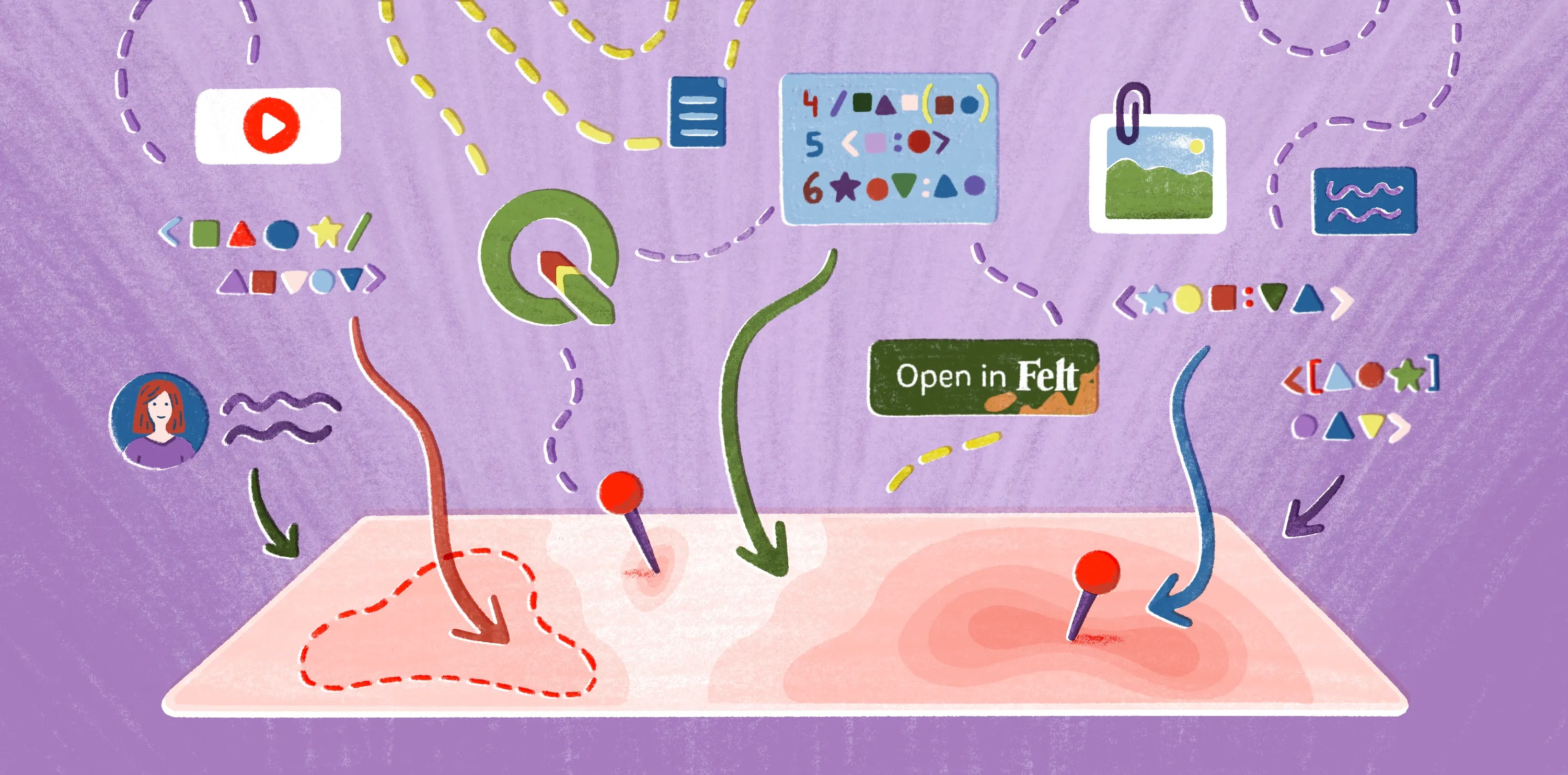
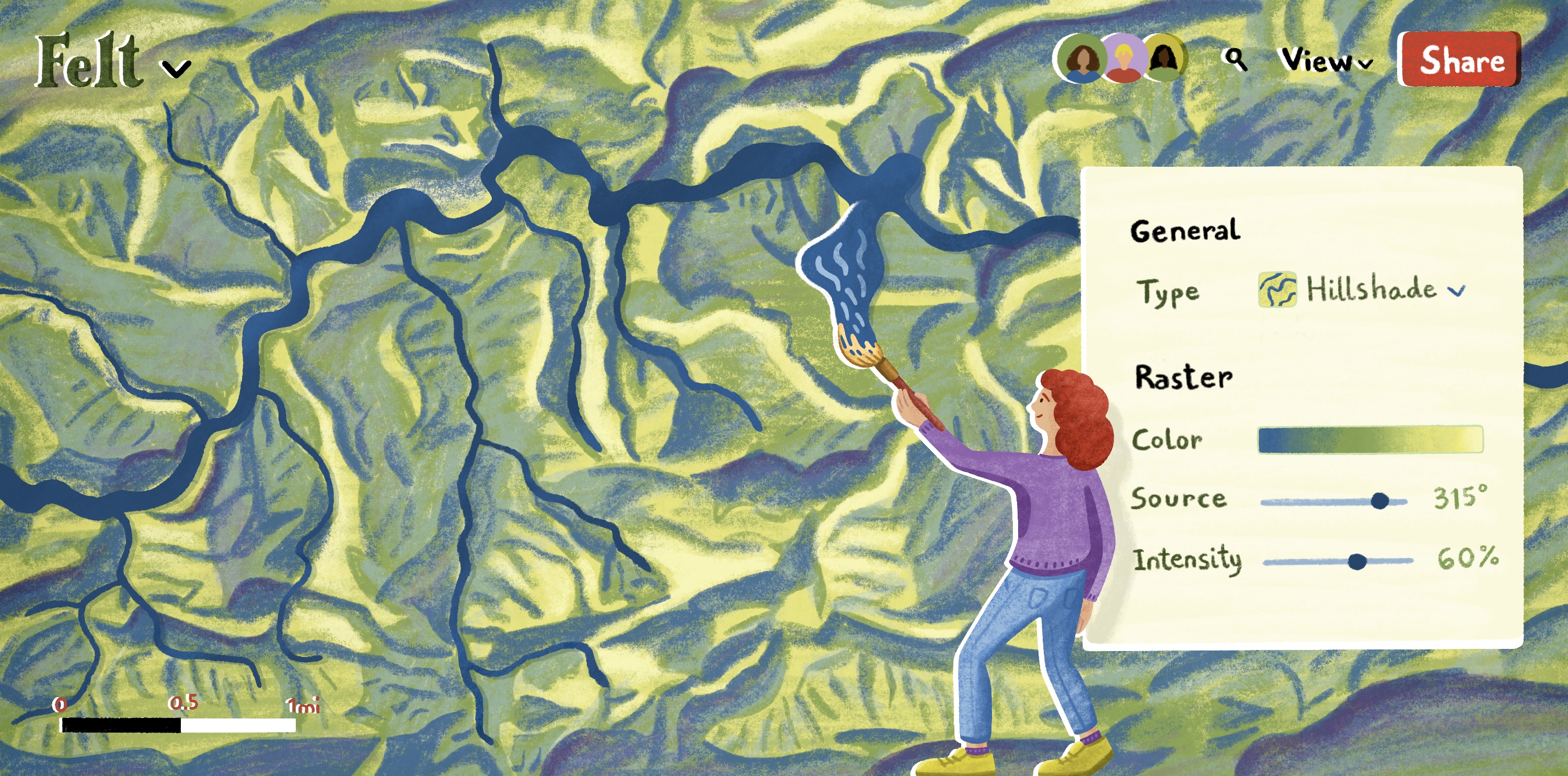
Work with georeferenced data in Felt
Georeferenced files are only useful if you can analyze, edit, and use them in practice. Felt glues the input and output together. Upload GeoTIFFs, DEMs, Raster GeoPackages, and georeferenced imagery directly to Felt — no pre-processing required. If CRS metadata is missing, Felt automatically infers the coordinate system based on the data's bounds, assuming latitude and longitude or Web Mercator meters, without manual configuration. Layer your raster data alongside vector datasets, then run spatial analysis like Buffer or Intersect across the combined map.
Felt lets teams collaborate on interactive maps in one intuitive platform. Simply share a link, and every teammate can jump in, annotate, and leave comments.
Sign up for free and bring your raster data into Felt.
Compare Felt using AI


.webp)

.jpg)

